- 您现在的位置:买卖IC网 > Sheet目录1012 > V23079D1001B301 (TE Connectivity)RELAY GENERAL PURPOSE DPDT 2A 5V
�� �
�
�Signal� Relays�
�P2� Relay� V23079� (Continued)�
�AXICOM�
�AXICOM�
�108� 3.00� 2.25� 9.2� -2.25� 128� 70�
�P2� -3.75�
�V23079� Relay� 70�
�AXICOM� 70� mW�
�218� 2.40� 1.80� 5.2� 1.80� 41� 140�
�Telecom-,� Signal� and� 64� Relays�
�208� 3.00� 2.25� 6.5� 2.25� 140�
�RF�
�U� max.� at� 0� A�
�211�
�4.50�
�3.38�
�9.8�
�3.38� U� max.� at� 2� x� 1� A�
�145�
�140�
�P2� V23079� 2� A� Relay�
�206� 9.00� 6.75� 19.6� 6.75� 578� 140�
�203� 12.00� 9.00� 26.15� 9.00� 1029� 140�
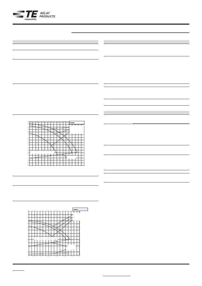
�Coil� Operating� Range�
�205�
�18.00�
�52.3�
�18.00�
�4114�
�140�
�70� mW�
�U� op.� U� max.� at� 0� A�
�U� max.� at� 2� x� 1� A�
�U� max.� at� 2� x� 2� A�
�2.2�
�140� mW�
�1� 2.6� U� nom.� nominal� coil� voltage�
�U� op.� min.� max.� at� 2� x� 1� A�
�U�
�U� max.� at� 2� x� 2� A�
�0.2�
�Ambient� Temperature� [°C]�
�code� voltage� voltage� Voltage� Voltage� resistance� power�
�0.8�
�VDC� op.� min.� max.� at� 0� A�
�VDC� VDC� VDC� U� ?±10%� mW�
�U�
�0.30� rel.� min.� max.� at� 45� 2� x� 1� A�
�008� 3.00� 2.25� 6.1� U� 200�
�U�
�006� 9.00� -30� -20� 6.75� 10� 20� 18.2� 50� 60� 70� 0.90� 100� 110� 120� 405� 140� 200�
�1.8�
�Ambient� Temperature� [°C]�
�between� open� contacts� 2000V� 2500V�
�U� nom� =�
�Nominal� coil� voltage�
�between� contact� and� coil� 108-98002� max.� 2pF�
�U� max.� =� between� adjacent� operative� range� of�
�according� to� IEC� /� EN� 60950� voltage)� when� coils� are�
�the� coil� voltage� (limiting�
�Nominal� coil� voltage� set� min.�
�U� nom� =�
�U� rel.� min.�
�=�
�Upper� limit� of� the� operative� range� of�
�IEC� the� coil� voltage� (reliable� release� voltage)� III� -� wash� tight�
�61810�
�RT�
�Degree� of� protection,� IEC� 60529� voltage)� when� coils� IP� 67�
�Coil Data� (continued)�
�Coil� versions,� bistable�
�Coil� Rated� Set� Limiting� Reset� Coil� Rated� coil�
�code� voltage� voltage� Voltage� voltage� resistance� power�
�VDC� VDC� VDC� VDC� ?±10%� mW�
�Bistable,� 1� coil�
�Telecom-,� Signal� and� RF� Relays�
�111� 4.50� 3.38� 13.85� -3.38� 289� 70�
�101� 5.00� 3.75� 15.33� 357�
�102� 6.00� 4.50� 18.5� -4.50� 514� 70�
�106� 9.00� 6.75� 27.75� -6.75� 1157� 70�
�103� 12.00� 9.00� 37� -9.00� 2057� 70�
�24.00 18.00 74�
�105� Coil� Operating� Range� -18.00� 8228� 70�
�Bistable,� 2� coil�
�219� 2.00� 1.50� 4.33� 1.50� 28� 140�
�3.4�
�3.2�
�3�
�2.8�
�2x� 2.6�
�201� 5.00� 3.75� 10.9� 3.75� U� max.� at� 178� 140�
�2.4�
�202� 6.00� 4.50� 13� 4.50� 257� 140�
�2.2�
�2�
�1.8�
�1.4�
�1.2�
�1�
�All� figures� are� given� for� coil� without� pre-energization,� at� ambient� temperature� +23°C.�
�Other� coil� voltages� on� request.�
�3.4� U� nom.� nominal� coil� voltage�
�0.8�
�3.2�
�3�
�0.6� min.�
�0.4�
�0.2�
�0�
�2.8�
�2.6�
�2.4�
�-40� -30� -20� -10� 0� 10� 20� 30� 40� 50� 60� 70� 80� 90� 100� 110� 120� 130� 140�
�2� Ambient� Temperature� [°C]�
�1.8�
�1.6�
�1.4�
�1.2� 2.8�
�U� max.� at� 0� A�
�0.8�
�2.4�
�0.6�
�2.2�
�0.4�
�2�
�0� 1.8�
�-40� -30� -20� -10� 0� 10� 20� 30� 40� 50� 60� 70� 80� 90� 100� 110� 120� 130� 140�
�1.6�
�1.4�
�voltagenominal� 1�
�Coil� versions,� 1.2� high� dielectric� version,� monostable,� overmolded�
�Coil� Rated� U� nom.� Operate� coil� Limiting� Release� Coil� Rated� coil�
�2.8�
�0.6�
�0.4�
�at� 2.20.2�
�2�
�001� 5.00� 3.75� 10.1� 0.50� U� max.� 125� x� 2� A� 200�
�002� 6.00� 4.50� 12.1� 0.60� 180� 200�
�0� 40� 90� 130�
�1.6�
�003� 12.00� 9.00� 24.2� 1.20� 720� 200�
�1.4�
�1.2�
�All� figures� are� given� for� coil� without� pre-energization,� at� ambient� temperature� +23°C.�
�Other� coil� voltages� on� request.�
�Insulation� Data� Standard� HDV�
�Initial� dielectric� strength�
�between� open� contacts� 1000V� rms� 1500V� rms�
�between� contact� and� coil� 1500V� rms� 1500V� rms�
�between� adjacent� contacts� 1000� V� rms� 1500V� rms�
�Initial� surge� withstand� voltage�
�according� to� Telcordia� TR-NWT-001089� (2/10μs)�
�108-98002� Rev.� E�
�between� contact� and� coil� 2500V� 2500V�
�between� adjacent� contacts� 2500V� 2500V�
�according� to� (10/700� μs� IEC� 60950)�
�between� open� contacts� 2000V� 2500V�
�between� contact� and� coil� 2500V� 2500V�
�between� adjacent� contacts� 2500V� 2500V�
�Initial� insulation� resistance� at� 500� Vdc� >� 10� 9� Ω�
�Capacitance�
�between� open� contacts� max.� 1pF�
�Rev.� E�
�max.� 1.5pF�
�Clearance� /creepage�
�1.3/2.5mm�
�continously� energized�
�min.� =� Data�
�U� op.� Other� Lower� limit� of� the� operative� range� of�
�the voltageEU(reliableoperate RoHS,�
�Material� compliance:� RoHS/ELV,� China� voltage)� REACH,� Halogen� content�
�refer� to� the� Product� Compliance� Support� Center� at�
�U U� min.�
�For� latching� relays� www.te.com/customersupport/rohssupportcenter�
�Ambient� temperature� -40� to� +85°C�
�=Lower oftheoperative�
�U� Category� of� environmental� protection� range� of�
�max.�
�the� coil� voltage� (limiting� are�
�resistanceenergized�
�Vibration� continously� (functional)� 35g,� 10� to� 1000Hz�
�Shock� resistance� (functional)�
�=Lowerlimitofthe sine)�
�U� op.� min.� IEC� 60068-2-27� (half� operative� range� of� 100g�
�thecoil�
�Terminal� type� voltage� (reliable� operate� voltage)� PCB-THT,�
�SMT� long� and� short� terminals�
�Weight� For� latching� relays� U� set� min.� resp.� U� reset� min.� max.� 2.8� g�
�Resistance� to� soldering� heat� THT�
�=Lowerlimitof�
�U� rel.� min.� IEC� 60068-2-20� the� operative� range� of� 265°C/10s�
�thecoilvoltage JEDECrelease�
�Moisture� sensitive� level,� (reliable� J-Std-020D� voltage)� MSL3�
�related� only� to� SMT� relays�
�packed� in� orginal� dry-packs�
�Ultrasonic� cleaning� not� recommended�
�Packaging/unit�
�THT� box/2000� pcs.�
�SMT� reel/2000� pcs.� or� 2500� pcs.�
�2.8�
�1�
�0.8�
�U� nom.� nominal� coil� voltage�
�200 mW�
�U� op.� min.� max.� at� 2� x� 1� A�
�2.6�
�2.4�
�2.2�
�0.6�
�0.4�
�0.2�
�U� max.� at� 0� A�
�U�
�U�
�U� rel.� min.� max.� at� 2� x� 2� A�
�2�
�1.8�
�1.6�
�1.4�
�1.2�
�0�
�-40� -30� -20� -10� 0� 10� 20� 30� 40� 50� 60� 70� 80� 90� 100� 110� 120� 130� 140�
�Ambient� Temperature� [°C]�
�0.8�
�0.6�
�0.4�
�0.2�
�U� op.� min.�
�U� rel.� min.� max.� at� 2� x� 2� A�
�0�
�1�
�2.8�
�2.6�
�2.4�
�2.2�
�2�
�U� nom.� nominal coil voltage�
�200� mW�
�U� max.� at� 0� A�
�U� max.� at� 2� x� 1� A�
�U�
�1.8�
�1.6�
�-40� -30� -20� -10� 0� 10� 20� 30� 40� 50� 60� 70� 80� 90� 100� 110� 120� 130� 140�
�Ambient� Temperature� [°C]�
�?� 2013� Tyco� Electronics� Corporation,� only� together� with� the� ‘Definitions’� section.� the� ‘Definitions’� section,� available� at�
�All� speci?cations� subject� to� change.� Consult� Tyco� Electronics� for� latest� speci?cations.� http://relays.te.com/definitions�
�a� TE� Connectivity� Ltd.� company�
�U� op.� min.�
�U� rel.� min.�
�2�
�1.4�
�1.2�
�10-2013,� Rev.� 1013� Datasheets� and� product� specification� Datasheets� and� product� data� is� subject� to� the�
�www.te.com� 1� U� nom.� nominal� coil� voltage� according� to� IEC� 61810-1� and� to� be� used� terms� of� the� disclaimer� and� all� chapters� of�
�0.8�
�0.6�
�0.4�
�0.2�
�0�
�Datasheets,� product� data,� ‘Definitions’� sec-�
�tion,� application� notes� and� all� specifications�
�are� subject� to� change.�
�5� of� 15�
�发布紧急采购,3分钟左右您将得到回复。
相关PDF资料
V23079E1206B301
RELAY GENERAL PURPOSE DPDT 2A 9V
V23079F1108B301
RELAY GENERAL PURPOSE DPDT 2A 3V
V23079G2016B301
RELAY GENERAL PURPOSE DPDT 2A 4V
V23079H1205B301
RELAY GEN PURPOSE DPDT 2A 24V
V23100V4315C010
RELAY REED SPDT 250MA 15V
V23148-B0008-A101
RELAY GEN PURPOSE SPDT 7A 48V
V23162B 721F104
RELAY GEN PURPOSE DPDT 5A 24V
V23162B721B110
RELAY GEN PURPOSE 4PDT 2A 24V
相关代理商/技术参数
V23079-D1001-B301
制造商:MA-COM 制造商全称:M/A-COM Technology Solutions, Inc. 功能描述:P2 Relay
V23079-D1001-B301
制造商:TE Connectivity 功能描述:RELAY SMD DPCO 5VDC
V23079-D1002-B301
制造商:MA-COM 制造商全称:M/A-COM Technology Solutions, Inc. 功能描述:P2 Relay
V23079D1003B301
功能描述:低信号继电器 - PCB 12VDC Non-latching 1 coil long pins P2
RoHS:否 制造商:NEC 触点形式:2 Form C (DPDT-BM) 触点电流额定值: 线圈电压:5 V 最大开关电流:1 A 线圈电流:1 A 线圈类型:Non-Latching 功耗:140 mW 端接类型:SMT 绝缘: 介入损耗:
V23079-D1003-B301
制造商:TYCO 功能描述:_
V23079D1003B301
制造商:TE Connectivity 功能描述:PCB RELAY
V23079D1005B301
功能描述:低信号继电器 - PCB 24VDC Non-latching 1 coil long pins P2
RoHS:否 制造商:NEC 触点形式:2 Form C (DPDT-BM) 触点电流额定值: 线圈电压:5 V 最大开关电流:1 A 线圈电流:1 A 线圈类型:Non-Latching 功耗:140 mW 端接类型:SMT 绝缘: 介入损耗:
V23079-D1005-B301
制造商:MA-COM 制造商全称:M/A-COM Technology Solutions, Inc. 功能描述:P2 Relay